Richocean Is China’s Trusted Supplier Of
Windows And Doors Manufacturer
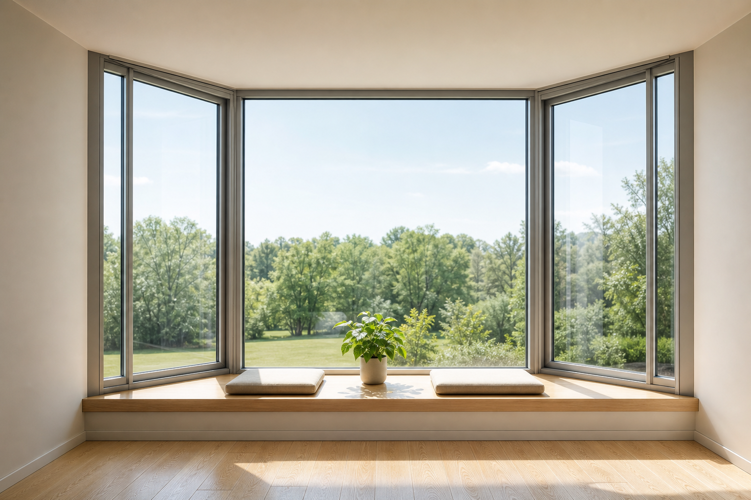
A bay window is a cantilever that happens to be glazed
Request a Quote →An aluminum glass bay window is usually specified as a window. It is not one. It is a projecting structure that carries a glazed enclosure, cantilevered or bracket-supported off the face of a building, with a floor that people sit on and a roof that collects snow and rain. The glazing is the smallest part of the problem.
This is why bay windows fail in ways that windows do not. They deflect, so the seal lines break and water arrives inside. Their brackets corrode at the interface with the aluminium, because two dissimilar metals were bolted together with no isolation. Their fixings pull out of a cavity wall that turned out to have insulation where the anchor needed solid backing. Their underside becomes the coldest surface in the room and grows mould. Every one of these is a structural or thermal failure, and none of them is visible in a glass specification.
What follows is the load path in order, the five ways to support a bay, the load cases that must be declared, and the deflection limit that decides whether the unit still performs after ten years.
Every kilogram of glass, every person sitting on the window seat, and every kilopascal of wind pressure follows the same route. The assembly is only as strong as its weakest link, and the weakest link is almost never the one that was specified.
| # | Link | What It Must Do | Common Weak Point |
|---|---|---|---|
| 1 | Glass pane | Carry wind pressure across its span and transfer it to all four edges | Thickness chosen by area rather than by the shorter span and the pressure zone |
| 2 | Glazing gasket and setting blocks | Hold the pane in the rebate, keep water off the edge, transfer load to the frame | Blocks omitted or placed at the corners, so the pane loads the gasket instead of the frame |
| 3 | Sash or fixed frame | Collect loads from all panes and pass them to the bay mullions | 1.4 mm wall thickness used where a heavier section is needed; corner cleats undersized |
| 4 | Bay mullions and the angled junctions | Resolve loads at the plane changes and keep the geometry square | The angled joint is a bending point, not a simple butt; a standard 90° cleat does not fit 30° or 45° returns |
| 5 | Bay floor deck or sill carrier | Carry dead and imposed load across the projection to the support | Deck specified for weatherproofing only, not for a seatable imposed load |
| 6 | Bracket, corbel or tie | Transfer the cantilever moment and shear into the host wall | Galvanised steel in contact with aluminium; corrosion at the bolt line |
| 7 | Fixings into the host structure | Anchor the bracket with adequate edge distance and embedment | Anchors landing in insulation or in a hollow block rather than in structural backing |
Two observations from the table. First, links 4 to 7 exist only because the window projects — a flush window has none of them, which is why a window schedule cannot cover a bay. Second, the failures cluster at links 6 and 7, which are usually designed by whoever is on site rather than by the window supplier, and which the supplier's quotation does not mention.
| Type | Geometry | Typical Projection | Structural Character |
|---|---|---|---|
| Box bay | Three planes, 90° returns, flat front | 400-700 mm | Straightforward cantilever; corners are standard 90° joints |
| Angled bay | Three planes, 30° or 45° returns | 350-600 mm | Angled joints need purpose-made cleats; the returns act as inclined struts |
| Bow bay | Four to six planes approximating a curve | 300-600 mm | Many short spans and many joints; load distribution is good, water management is hard |
| Oriel | Projecting from an upper floor, no ground support | 400-800 mm | Fully bracket or corbel dependent; the highest load path demand of the group |
The bow bay illustrates the trade-off clearly. Because it has more planes, each pane is smaller and each span shorter, so the glass and frame see lower stress than in a box bay of the same overall width. But it has proportionally more joints, and every joint is both a structural connection and a water path. Bow bays do not usually fail structurally; they leak at the segment junctions.
| Support Method | Practical Projection | Seatable? | Thermal Bridge Severity | Corrosion Risk |
|---|---|---|---|---|
| Steel cantilever bracket from the wall face | Up to about 700 mm, subject to calculation | Yes, if designed for imposed load | High — steel passes straight through the insulation line | High if galvanised and in contact with aluminium |
| Masonry corbel or built-out pier | Wide; limited by the masonry design | Yes | High unless the corbel is insulated and broken | Low for the corbel; the fixings into it still need the right anchor |
| Tie rod or chain suspended from above | Moderate; carries tension not bending | Limited — deflection under imposed load is hard to control | Moderate — a single penetration point | High; the rod is exposed and is usually the visible failure |
| Ledger or sill carrier onto a ground-floor slab or wall below | Wide; the most robust option | Yes | Moderate; can be insulated at the bearing | Low |
| Fully cantilevered structural slab extension | Set by the structural engineer, not the window supplier | Yes | Highest — a concrete slab projecting outside the insulation is a major linear bridge | Low for structure, high for condensation |
The choice is rarely free. Where an oriel sits above a finished exterior with nothing below to bear on, brackets or ties are the only options, and both come with a thermal bridge that has to be detailed deliberately rather than accepted by default. Where a ground-floor bay sits over a slab, the ledger route is cheaper, stiffer and drier, and should be asked for.
| Load Case | Typical Basis | Why It Is Missed |
|---|---|---|
| Dead load | Glass about 25 kg/m² per 10 mm thickness, plus frame, deck and finish | Triple glazed or laminated units in a bay add up quickly; the deck finish is often added after the bracket was sized |
| Imposed load on the window seat | Commonly 1.5-2.0 kPa where people can sit or stand | The single most omitted case. Everyone intends to sit there; nobody writes it down |
| Snow on the bay roof | EN 1991-1-3 or local code, by ground elevation and roof pitch | Bay roofs are near-flat and collect drift from the wall above |
| Wind pressure and suction | EN 1991-1-4 or AS/NZS 1170.2; 2.0-3.0 kPa common on exposed low-rise | Suction governs the tie and bracket tension case; projections accelerate local flow at corners |
| Thermal movement | Aluminium expands about 2.4 mm per metre per 100 °C | A 3 m bay head moves several millimetres seasonally; restraint turns movement into stress at the joints |
| Construction and maintenance access | Point load from ladders, cleaners, or someone standing on the sill | Not a design load in most codes, but it is a real one and it is applied at the least favourable position |
Strength and stiffness are different requirements, and bays are usually governed by stiffness. A bracket can be strong enough not to break while being flexible enough to move several millimetres under load. That movement is what breaks the unit over time.
A practical target is span/200 or tighter for a seatable bay, and span/175 to span/200 for the roof and head members. Excess deflection produces three consequences, in this order:
The order matters for diagnosis. If a bay leaks at one corner, check deflection and level before replacing the gasket. A new gasket fitted to a distorted frame will fail the same way.
Steel brackets under aluminium windows corrode, and they corrode faster than either material would alone. Aluminium sits well above carbon steel in the galvanic series, so when the two are in electrical contact in the presence of an electrolyte — rain, condensation, coastal salt — the steel becomes the anode and is consumed. The bracket loses section at exactly the point where it carries the highest stress, usually at the bolt line and at the weld.
Bracket capacity is worthless if the anchor behind it is inadequate, and the anchor's capacity is set by the substrate, which the window supplier usually does not know. Five situations cover most projects.
| Substrate | Anchor Basis | Critical Check |
|---|---|---|
| Cast concrete or structural column | Mechanical or bonded anchor, capacity from the manufacturer's data | Edge distance and spacing; cover to reinforcement |
| Solid masonry or brick | Anchors rated for masonry, with a pull-out test on site | Mortar joints are weaker than the unit; avoid anchoring into a bed joint |
| Hollow block or perforated brick | Bonded anchor with a screen sleeve, or a through-bolt with a spread plate | Expansion anchors can burst the web; the failure is sudden |
| Timber or light steel frame | Fixing into a stud or a noggin added for the purpose | Fixing into sheathing alone has almost no capacity; the stud positions must be located, not guessed |
| Insulated cavity wall | Long anchor reaching structural backing through the insulation and cavity | The most common failure. An anchor gripping only the outer leaf will pull out under wind suction |
The insulation cavity row deserves emphasis because it fails in the worst way. The bay holds fine under dead load, which is vertical and modest, and pulls away under wind suction, which is horizontal, cyclic and at its highest during a storm. The anchors were never tested in that direction.
A bay window puts a floor, a roof and a set of frames outside the building's insulation envelope. That is the definition of a thermal bridge, and it is unavoidable in principle — it can only be reduced by detailing. The consequence is predictable: the underside of the bay floor and the internal reveal become the coldest surfaces in the room, and in cold weather they fall below dew point first.
| Bridge Location | Mechanism | Mitigation |
|---|---|---|
| Bay floor deck | Conductive path from the interior floor out to the cold underside | Insulation beneath the deck, and a structural break at the wall line where the support method allows |
| Steel bracket | Steel is roughly 1,000 times more conductive than insulation; each bracket is a spike of heat loss | Isolation pads at the wall and deck interfaces; fewer, larger brackets rather than many small ones |
| Bay roof and head | Thin construction with little room for insulation, and solar gain on top | Insulated deck panel, ventilated air gap where geometry allows |
| Frame sections | Aluminium conducts; without a break the frame is the cold surface | Continuous PA66-GF25 thermal break through the mullions, including at the angled junctions where breaks are often interrupted |
| Wall junction and reveal | Linear bridge where the bay meets the host wall; the usual first mould line | Continuity of insulation around the opening, assessed under EN ISO 10211 with the psi-value stated |
The declaration to ask for is a Uw for the bay assembly as built, including the angled mullions, not the centre-of-glass value and not the Uw of the same glazing in a flush window. Those two numbers are always better and neither describes the bay.
Wind pressure is not uniform around a projection. Codes assign higher local pressures to corners and edges, and a bay window is mostly corners. Three consequences follow.
Where the bay roof is glazed rather than solid, the overhead glazing rules from our sunroom compliance article apply in full: laminated inner ply so fragments stay supported after breakage, and heat-soaked tempered outer ply where tempered glass is used.
| Parameter | Practical Limit | What Happens Beyond It |
|---|---|---|
| Projection | About 700 mm on brackets without a dedicated calculation | Bracket moment rises linearly; deflection governs before strength |
| Plane width | Set by glass thickness and the frame's span capacity | Glass thickness and cost rise steeply; the front plane usually governs |
| Return angle | 30° or 45° with purpose-made cleats; below about 25° the joint weakens | Acute corners cannot carry the load path and cannot be sealed reliably |
| Bay roof pitch | Enough fall to shed water and snow; flat roofs need a designed drainage path | Ponding adds static load, holds debris and accelerates coating failure |
| Head projection over the bay | A flashing or overhang that throws water clear of the frame | Without it, run-off tracks down the glass and into the head joint under wind-driven rain |
Water management on a bay follows the drained-and-ventilated principle rather than the face-sealed principle. Every joint that can take water should have a path for that water to drain out and a path for air to equalise the pressure behind it. On a bow bay this means each segment junction needs its own drainage, because water that enters one segment must not be able to travel to the next. EPDM gaskets are used because they retain elasticity across the temperature range and resist UV and ozone; they are a maintenance item with a finite life, and the compression must be checked after any adjustment to the frame or the deck.
Bays are almost always supplied in sections and assembled on site, because a fully assembled three- or six-plane unit will not travel or fit through an opening. The section joint is therefore both a structural connection and a water path, and it is made in site conditions by installers who may not have the drawing that explains how it was designed.
| Standard | Covers | Applies To |
|---|---|---|
| EN 1999 (Eurocode 9) / AS-NZS 1664 | Design of aluminium structures | Bay frame, mullions and deck members |
| EN 1991-1-1 / -1-3 / -1-4 or AS/NZS 1170 | Imposed, snow and wind actions | The bracket, the deck and the fixings |
| EN 1993 / AS 4100 | Design of steel structures | Steel brackets, corbels and tie rods |
| AS1288 / IBC 2407 | Glass in buildings; safety glazing in critical locations | Low-zone glazing at the window seat, and any glazed bay roof |
| AS2047 / EN 14351-1 | Window performance: air, water, wind, operating force | The operable sashes within the bay |
| EN ISO 10077 / EN ISO 10211 | Thermal transmittance and thermal bridges | Uw of the assembly; psi-value at the wall junction |
The trial assembly step is the one to insist on. A bay's angled joints cannot be proved on site, and a factory trial assembly is the only point at which an error in a cleat angle or a section length can be found cheaply. Where a bay is shipped direct to site without one, the first time the sections are brought together is in front of an opening, at height, on the day the crane is hired.
| Configuration | Basis | Indicative FOB (USD) |
|---|---|---|
| Box bay, three planes, fixed, non-thermally broken | 6063-T5/T6, double glazed, projection to 500 mm | $210-330 /m² of elevation |
| Box bay, thermally broken, Low-E argon | Continuous PA66-GF25, seatable deck included | $310-480 /m² |
| Angled bay, 30° or 45° returns | Purpose-made angle cleats | $350-540 /m² |
| Bow bay, four to six planes | Segmented junctions with individual drainage | $420-660 /m² |
| Oriel, upper floor, fully bracket supported | Structural calculation per project | $520-850 /m² |
| Steel bracket set, galvanised | Per bay, load rated | $95-220 /set |
| SUS316 bracket upgrade with isolation pads | Coastal and exposed sites | +$140-320 /set |
| Insulated bay deck and roof panel | Reduces the underside bridge | +$85-190 /m² |
| Laminated safety glazing in the low zone | Required where the seat is used | +$38-95 /m² |
| Motorised bay head vents with RS485/KNX control | Night cooling and automated ventilation | +$420-1,200 /bay |
Prices are indicative 2026 factory FOB ranges for project volumes, excluding freight, site anchors, foundation work and installation. Bay window pricing is normally quoted per square metre of elevation with a minimum per-unit charge, since section joints, angle cleats and the trial assembly are one-off costs. Final quotation depends on bay type and plane count, projection, support method and load case, glass build per plane, thermal break continuity, bracket grade, finish, and the documentation package required. Contact Rogenilan Windows Doors for a project-specific calculation and quotation.
If it projects and anything sits on it, yes. A bay is a cantilever carrying dead, imposed, snow and wind loads into a host wall of unknown capacity, and the glass specification alone says nothing about any of it. The calculation should cover the deck, the bracket, the fixings and the frame members, and should state the deflection result against the limit applied.
Usually deflection rather than a failed gasket. When the deck or frame distorts, gasket compression is lost at one corner and increased at the opposite one, and a second consequence is that the sill loses its outward fall and holds water. Check the level across the bay and the compression with a paper test before replacing seals, and address the support if the frame is out of level.
It can, if it was designed for it. The imposed load case for a seatable bay is commonly 1.5 to 2.0 kPa, and it governs the deck, the bracket and the anchors. Many bays are built with a deck intended as a weather seal and a finish only, and they are perfectly safe until someone sits on them. State the intent in the enquiry so the deck is specified accordingly.
Not always, but they will if the contact is not managed. Aluminium and carbon steel form a galvanic cell when wet, and the steel is consumed at the bolt line and at welds. Stainless brackets, isolation pads or insulating washers, and treated weld areas all reduce the rate substantially. The practical rule is that a bracket which cannot be inspected should be stainless.
On brackets, around 700 mm without a dedicated calculation, and further with one. Beyond that the bracket moment and the deflection both rise, and the answer usually becomes a corbel, a ledger onto something below, or a structural slab extension designed by the project engineer. The projection is a structural decision before it is a window decision.
Structural calculation covering deck, bracket and fixings · stated deflection against span/200 · SUS304/316 brackets with isolation pads · 6063-T5/T6 frames, 1.4-5.0 mm wall thickness · continuous PA66-GF25 breaks through angled mullions · laminated low-zone safety glazing · EPDM seals with drained-and-ventilated joints · factory trial assembly · SIEGENIA, ROTO and HOPO hardware · 2026 FOB pricing in 24 hours.
Request a Quote →Related Articles
Socials

 Casement
Windows
 Sliding
Windows
 Awning
Windows
 Single/Double
Hung Windows
 Tilt
& Turn Windows
 Bay
& Bow Windows
 Folding
Windows
 Picture
Windows
 Specialty
Windows
 Exterior Doors
 Stacking Doors
 Folding
Doors
 Double Doors
 Casement
Doors
 Sliding Doors
 Skylight
 Sunroom
 Garage
Door
 Curtain
Wall
 Glass
Railing